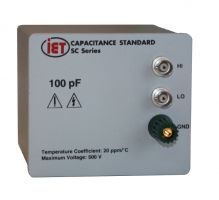
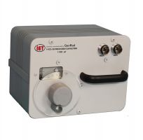
- Available in values from 0.001 pF - 1000 pF
- Excellent performance at high frequencies
- ISO-17025 accredited calibration included with the standard
- NEW 1403-1pF-BNC and 1403-0.001pF-BNC versions
Consult IET Labs, Inc for pricing information
The IET Labs/GenRad 1403 Standard Air Capacitors are stable, The IET Labs/GenRad 1403 Standard Air Capacitors are stable, three-terminal standards in values from 0.005 pF to 1000 pF.
The capacitance change is less than 0.01% at frequencies up to 2 MHz for 1 pF and 200 kHz for 1000 pF standard making the standard ideal for verifying LCR meters and bridges at frequencies other than 1 kHz.
See the application note for more information on calibration of LCR meters using the 1403 Standard Capacitors at 1403 Air Capacitors for Calibration of the 7660 Precision LCR Meter and other LCR meters
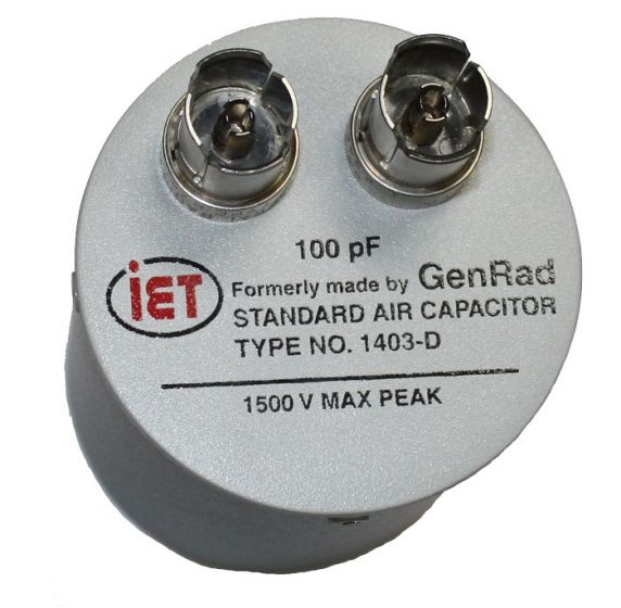
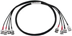
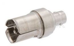
Their terminals are arranged to plug directly into the UNKNOWN terminals of the Type 1620 Capacitance Bridge or equivalent such as AH2500A Ultra Precision Capacitance Bridge. The GenRad/IET Labs 1403s traditionally have been manufactured with GR 0874 connectors. Newer 1403-BNC versions are now available with BNC connectors for easy connection to a wide variety of LCR Meters and bridges.
Features of the 1403 Air Capacitor:
- Stable to better than 0.05%/year
- Excellent performance at high frequencies
- Extremely low dissipation factor
- Low temperature coefficient
- Well documented performance by nationally recognized laboratories
Design
The Types 1403-A, 1403-D, and 1403-G have nominal values of 1000 pF, 100 pF, and 10 pF, respectively. Their construction follows a conventional design, similar to that of the 1404 Series of Capacitance Standards, consisting of interleaved stacks of aluminum plates rather than the invar plates used in the 1404 Series. Each plate is insulated from the supporting panel and housing.
The stacked plate construction is not practical for values of 1 pF and below, so an aperture design is used. In this type of capacitor, the two electrodes are isolated from each other by a guard plate between them. The shielding provided by this plate is designed to minimize stray capacitance between the active electrodes to nearly zero.
The magnitude of capacitance between the electrodes is determined by the opening (aperture) in the guard plate along with the spacing between the two electrodes.
The effective area of the aperture is slightly smaller than what would be determined by its diameter. This reduction in effective area can be described as “negative fringing” of the electric field.
Since there is no solid dielectric in the direct capacitance field, the losses in the 1403 capacitors are extremely low, typically < 20 ppm (unitless).
Figure 1. Aperture design on the left and the other 2 are conventional stacked plates
For measurements at 100 pF and below, a three-terminal connection increases accuracy by eliminating uncertainty introduced by the capacitance between the capacitor terminals and ground. This improves the performance of the capacitor when used with LCR meters.
The 1403 Standard Air Capacitors have been extensively studied. The performance over frequency, barometric pressure and temperature have been well-documented, by articles such as the two shown below.
The paper The Measurement and Uncertainty of Air Dielectric Capacitors from 1 kHz to 10 MHz provides extremely useful information on the change of capacitance vs barometric pressure, relative humidity and temperature for the 1403 Series Air Capacitors. (Click on View Conference button on left side of the page to see presentation.)
The paper Establishment of 2TP air-dielectric capacitance standard for 1 pF, 10 pF, 100 pF and 1000 pF in the frequency range up to 10 MHz by resonance frequency at NIMT provides information on calibration of 1403 Series Air Capacitors at up to 1 MHz for use in calibrating LCR meters. IET Labs calibrates the 1403s at it's facility in West Roxbury, MA. The approximate elevation is 115 feet (35 meters) above sea level. Given this elevation the approximate air pressure is 101000 Pa.
GenRad 1403 Series High Frequency Standard Capacitor Basic Specifications
Calibration: A certificate of calibration is supplied with each unit giving the measured capacitance at 1 kHz and at a specified temperature. The measured value is the direct capacitance between shielded terminals when the capacitor has at least one lead completely shielded and its case connected to a guard point.
The calibrated capacitance value is obtained by direct measurement using an AH2700A Capacitance Bridge or comparison, to a precision better than ±(0.01% + 0.00001 pF), with standards whose calibrated values are known to an accuracy < 10 ppm, and are periodically calibrated traceable to the SI through a national metrology institute (NIST, NRC, etc).
Stability: Capacitance change is less than 0.05% per year.
Temperature Coefficient of Direct Capacitance: Typically 20 to 40 ppm per degree between 20° and 70°C. The larger coefficients apply to the smaller capacitance values
Terminals: GR874 Coaxial Connectors, which provide complete shielding of the leads Two bnc-f connectors for -BNC versions